Launch Angle
Field report — updated 22 July 2026.
How we measure launch angle with a 60 GHz radar. A plain-language guide to the OPS243 + TI IWR6843 pipeline, the late-flight algorithm we call LCMF-v1, what three TrackMan sessions taught us, and how we plan to improve coverage without hiding quality.
| Angle sensor | TI IWR6843 |
| Speed sensor | OPS243 |
| Estimator | LCMF-v1 |
| Validation | Three indoor TrackMan sessions |
Explain it like I’m five
We watch the ball several times, keep the clearest pictures, and ask five judges where it is going.
The OPS radar tells us how fast the ball is moving. The TI radar takes a short movie made of radio echoes. We find the little streak that moves away from the tee, keep the clearest moments from each frame, and pay extra attention to the later part of the flight because the ball is farther from the club, golfer, and impact mess.
Five slightly different physics models each estimate launch angle. We average their answers and use the measured mount geometry directly. If the radar movie is strong, the UI shows the measured radar angle. If the movie is weaker but still plausible, we want to show it as a lower-confidence two-dot radar read. If the radar cannot honestly follow the ball, the UI labels a normal club-based estimate instead.
The important idea
Many looks + multiple models + honest confidence, never a hidden adjustment that quietly fits one golfer or one club.
Where we are
The short version
| Value | Meaning |
|---|---|
| 0.83° | combined Iron/Wedge MAE across two indoor TrackMan validation sessions |
| 87.4% | strict LCMF-v1 coverage on Iron/Wedge shots, 76 of 87 |
| 0.67° | p50 absolute error; half of covered Iron/Wedge shots were inside this |
| -0.04° | bias on covered Iron/Wedge shots, effectively centered |
For Iron/Wedge shots, the current pipeline is inside the 1° target on the shots where the radar has enough clean evidence. Driver and Mis Hits are tracked separately because they expose different engineering problems. The next job is widening coverage and hardening setup inputs so the same result travels to different builders, mats, rooms, and ranges.
State the problem
We need ball and club direction in a brutally short window
OpenFlight has to measure vertical launch, horizontal launch, and eventually useful club-delivery signals while the ball is only a few feet from the radar. Indoors, a fast driver can hit a net or screen tens of milliseconds after impact. That leaves very little clean flight, and the earliest echoes are exactly where the club, hands, tee, ball, floor reflection, and impact noise overlap.
The K-LD7 taught us the core lesson: one transmitter, a slower frame cadence, coarse range separation, and one or two useful post-impact looks were not enough to consistently separate the real ball path from multipath and blind-zone behavior. It could look good on selected shots, but it did not create a robust 1° path against TrackMan, the gold-standard source of truth for launch-monitor validation.
Note
The product problem is not just “detect a ball.” It is detecting the right moving echo, proving it is the ball, modeling the ground-reflected copy, and reporting confidence honestly when the evidence is thin.
Why this radar
The IWR6843 gives us enough raw evidence to model the mess
We selected TI’s IWR6843 because it can capture coherent complex radar data across multiple receive channels at a much faster cadence than the K-LD7 setup. The IWR6843LEVM board was the practical evaluation platform: available hardware, known antenna geometry, TI tooling, and enough on-chip L3 memory to hold a compact radar cube from the shot.
We created and uploaded custom firmware that turns the TI board into a short “radar movie” recorder. Instead of asking the radar to make a decision live, the board saves 12 tightly spaced snapshots of the ball leaving the tee. Each snapshot keeps detailed antenna information, so our software can later follow the ball moving away and separate it from the floor reflection, club, and impact noise.
| Capability | Why it matters | Current use |
|---|---|---|
| Fast frame cadence | More looks before the net or screen contaminates the track. | 12 snapshots over roughly 72 ms in the current custom firmware. |
| Fine range bins | Direct and floor-reflected paths can separate in range as the ball leaves the tee. | 3.2 GHz sweep, about 4.7 cm bins. |
| Complex antenna channels | Phase across the array carries angle information even when amplitude is messy. | Eight vertical virtual channels from TX1 + TX3 and four RX. |
| L3 rolling buffer | We can keep raw shot evidence and improve offline without reflashing for every idea. | 786,452-byte dump per trigger, drained by the Pi. |
OPS + IWR6843
Two radars, each doing the job it is best at
The one-chip goal was useful while learning the TI sensor, but it is no longer the product direction. OPS speed has been highly consistent and does not need to be replaced. The TI board is now focused on the measurements its antenna array can add: vertical launch angle today, and eventually aim direction and club path.
OPS243
Measures ball and club radial speed from its rolling buffer. This remains the speed authority.
TI IWR6843
Stores a 72 ms coherent radar movie across eight virtual vertical antenna channels.
OpenFlight UI
Combines OPS speed with TI launch angle. If TI has no read, the shot still appears with an estimated angle.
Why the TI chip changed the problem
The K-LD7 could usually see only one or two useful frames before the indoor net stopped the ball. It also had coarse range resolution and only a two-element angle view, so a clean ball echo and a floor reflection could blend into one believable but wrong angle.
The custom firmware saves a compact, high-detail radar movie: 12 snapshots of the ball leaving the tee, spaced about 6 ms apart. Each snapshot uses multiple antenna views and fine distance slices, which gives the software enough evidence to model the floor reflection instead of pretending it is not there.
Note
The rolling buffer is the enabling trick. This is similar to how OPS keeps a rolling speed buffer: the radar is always recording, and impact tells the system which recent slice matters. A sound trigger connected to the Pi freezes the TI radar movie after impact, preserving the last 72 ms of raw antenna data. The Pi then drains the 786,452-byte dump over UART in about 7.6 seconds. We accept the delay because we keep the raw evidence for every shot.
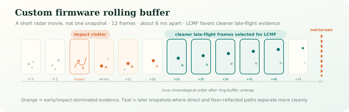
Rolling buffer mental model. The radar is not trying to decide launch angle from one echo. It stores a short radio movie, then LCMF looks for the portion where the ball has separated from the impact mess but has not yet reached the net or screen.
LCMF-v1
What the algorithm actually does
LCMF means Late-Flight Complex Multipath Fusion. “Late-flight” means it favors the cleaner second half of the captured ball flight. “Complex” means it keeps both amplitude and phase from every antenna. “Multipath” means direct and floor-reflected echoes are modeled together. “Fusion” means no single model gets to decide the answer.
Freeze both buffers
The same impact edge timestamps the OPS shot and starts the TI dump. Matching is normally within a few milliseconds.
Find the outward streak
Static clutter is removed. The tracker follows a target moving outward through range over time rather than trusting aliased Doppler speed.
Balance the frames
Keep snapshots with strength score ≥ 8 and range ≤ 4.7 m, then retain at most the strongest four from each frame. One noisy frame cannot dominate.
Use OPS speed as the guide
The independently measured OPS ball speed defines the candidate trajectory. TI’s local range-walk velocity handles the small timing correction between transmitters.
Ask five physics models
Two models compare the eight antenna channels across all balanced snapshots. Three inspect the direct and reflected range structure in the chronological late half.
Fuse and report
Each model receives exactly 20% weight. Their mean is the LCMF angle. The production path favors measured setup geometry and the same estimator rules for every club.
| Model family | Plain-language question | Data used |
|---|---|---|
| Two channel models | Which launch trajectory best explains the phase pattern across the antenna array when direct and floor paths are allowed? | All balanced snapshots |
| Three fast-time models | Which trajectory best explains the small range separation and mixture of direct and reflected echoes around the tracked ball? | Chronological second half |
| Equal fusion | What answer survives five different assumptions instead of winning one hand-picked model? | 20% per component |
Real captured shots
Which frames are selected, and why late flight helps
The gray marks below are usable snapshots along three real TrackMan-paired ball tracks. Orange circles are the strongest four retained from each frame. Teal dots are the chronological late half used by the three fast-time models. Frame numbers wrap because the radar memory is a ring; the horizontal time axis is the true order.
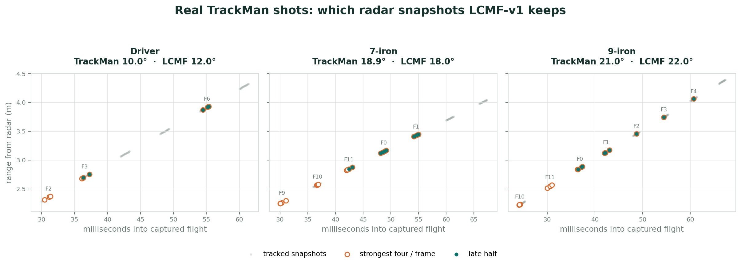
Actual July 14 captures. The driver has only three clean frames and is therefore the hardest case. The 7-iron and 9-iron offer more looks across the flight. Late snapshots are not automatically “correct”; they are simply less contaminated by impact, club, hands, and tee while providing more direct-versus-ground path separation.
This selection is deliberately boring: no club-specific timing window, no TrackMan input, and no hand-picked frame number. The same strength, range, per-frame balancing, and chronological-half rules run on every shot.
Setup calibration
The radar is accurate only if the setup geometry is honest
The biggest lesson from the first two validation sessions is simple: the algorithm can follow the ball, but it needs the real-world setup described correctly. Mount tilt, radar height, tee distance, ball height, mat height, and net distance all affect where the radar expects the direct and floor-reflected echoes to appear.
When those inputs are right, the same LCMF-v1 estimator produces a centered result across two indoor TrackMan sessions without per-club tuning. When those inputs are wrong, the error can look like a radar problem even though the underlying ball track is still present.
| Setup input | Why it matters | Product plan |
|---|---|---|
| Mount tilt | Defines how the antenna frame maps into the golfer's launch frame. | Measured setting first; later add an on-rig level sensor. |
| Tee distance | Changes the expected direct/reflected path geometry during the first few feet of flight. | Support measured distance and radar-assisted setup warnings. |
| Mat and ball height | An elevated mat changes the ball height relative to the radar and the floor reflection. | Store ball height and mat/surface height separately. |
| Net or screen distance | Defines how much clean late flight exists before impact with the screen or net. | Log it per session and use it when selecting late frames. |
What remains true
- learnedThe estimator is extracting stable ball-angle information from the TI radar movie.
- not solvedWe still need to make these setup measurements easy enough for normal builders, not just people who lived inside the test sessions.
TrackMan validation
Two TrackMan sessions are the current accuracy baseline
The headline below combines two indoor TrackMan validation sessions. Driver and Mis Hits are separated so the main number describes Iron/Wedge launch-angle performance rather than hiding known edge cases.
| Group | Shots | Covered | Coverage | MAE | p50 | p75 | p90 | Bias |
|---|---|---|---|---|---|---|---|---|
| Iron/Wedge headline | 87 | 76 | 87.4% | 0.83° | 0.67° | 1.20° | 1.80° | -0.04° |
| First validation session Iron/Wedge | 41 | 39 | 95.1% | 0.83° | 0.78° | 1.25° | 1.81° | -0.10° |
| Second validation session Iron/Wedge | 46 | 37 | 80.4% | 0.84° | 0.59° | 1.19° | 1.70° | +0.02° |
Note
How to read absolute error: MAE is the average distance from TrackMan, ignoring sign. p50 means half the covered shots were closer than that error. Bias keeps the sign and tells us whether the whole group is systematically high or low.
Current 18-frame firmware confirmation
A third indoor TrackMan session on July 22 tested the production firmware in this report: 3 TX, 12 loops, 18 frames, 4 ms spacing, and moving 53-bin windows. Twenty shots had matched OpenFlight and TI captures and therefore formed the valid radar denominator; five additional TrackMan swings had no corresponding OpenFlight capture and were not counted as estimator misses.
Using the physically measured 12.4° mount geometry, the matched group produced approximately 0.68° launch-angle MAE. An earlier block in the same session independently suggested about 12.3°; applying that geometry to the later good-shot block produced approximately 0.47° MAE. That temporal result is encouraging, but it remains diagnostic rather than the headline because the tilt candidate was inferred inside the same session. The conservative conclusion is that denser, cropped firmware preserved sub-1° vertical accuracy while adding more frames and the third transmitter.
Iron/Wedge breakdown by club
The 9-iron table excludes a same-day experimental transmitter-order test from the headline. That experiment is useful firmware evidence, but it should not be mixed into the normal production score.
| Club | Good shots | Covered | Coverage | MAE | p50 | p75 | p90 | Bias |
|---|---|---|---|---|---|---|---|---|
| Sand wedge | 17 | 15 | 88.2% | 0.67° | 0.46° | 1.06° | 1.58° | -0.22° |
| 9-iron | 27 | 25 | 92.6% | 0.89° | 0.81° | 1.18° | 1.73° | +0.24° |
| 7-iron | 21 | 18 | 85.7% | 0.91° | 0.49° | 1.15° | 1.88° | -0.06° |
| 5-iron | 22 | 18 | 81.8% | 0.82° | 0.69° | 1.31° | 1.84° | -0.25° |
Driver separated
| Group | Shots | Covered | Coverage | MAE | p50 | p75 | p90 | Bias |
|---|---|---|---|---|---|---|---|---|
| Driver | 22 | 18 | 81.8% | 3.55° | 1.31° | 1.82° | 15.57° | +3.39° |
| First validation session driver | 9 | 5 | 55.6% | 1.58° | 1.37° | 1.85° | 2.77° | +1.08° |
| Second validation session driver | 13 | 13 | 100.0% | 4.31° | 1.21° | 1.71° | 15.68° | +4.27° |
Note
Driver is not the same failure as irons. The second-session driver misses were mostly false acceptance of slow/ghost tracks. Raw replay showed the real fast ball in the frames, so the immediate fix is an OPS-vs-TI speed gate and a low-confidence fast-track recovery path.
Mis Hits separated
| Group | Shots | Covered | Coverage | MAE | p50 | p75 | p90 | Bias |
|---|---|---|---|---|---|---|---|---|
| Mis Hits | 19 | 13 | 68.4% | 2.20° | 1.16° | 3.07° | 5.10° | -0.54° |
| First validation session Mis Hits | 8 | 7 | 87.5% | 2.40° | 1.29° | 3.81° | 4.83° | -0.15° |
| Second validation session Mis Hits | 11 | 6 | 54.5% | 1.98° | 0.78° | 1.43° | 4.54° | -1.00° |
| Skulls / very low launch | 5 | 5 | 100.0% | 6.00° | 2.07° | 3.51° | 15.47° | +4.31° |
These groups are still product-critical because real golfers hit them. They are separated here because they require different engineering: TX2 aim for directional Mis Hits, low-launch/impact-clutter logic, and OPS speed agreement for driver.
Next steps
Increase coverage, add club data, and harden the setup inputs
The strict LCMF-v1 gate is doing the right thing for accuracy, but it leaves some real ball flights unreported. The first validation session already had strong strict coverage after the setup geometry was cleaned up. The second session showed the more practical product problem: a relaxed pass can recover no-reads, but those reads should enter the UI as measured lower-confidence angles rather than being mixed into the high-confidence lane.
RMS is a “how messy was the fit?” score. Lower RMS means the radar snapshots line up neatly with one clean ball path. Higher RMS means the ball is probably there, but the evidence is noisier, weaker, or more mixed with reflections. Relaxing the RMS limit lets us accept more of those imperfect radar tracks, which increases coverage, but it also increases the chance that a recovered angle is a little farther from TrackMan.
The product answer should not be “lower the bar and call everything high confidence.” The product answer should be a second lane: measured, but lower confidence.
| Mode | Iron/Wedge coverage | MAE | p50 | p75 | p90 | New recovered reads | Recommended UI |
|---|---|---|---|---|---|---|---|
| Combined strict LCMF-v1 | 76 / 87 · 87.4% | 0.83° | 0.67° | 1.20° | 1.80° | 0 | 3 dots |
| First-session strict | 39 / 41 · 95.1% | 0.83° | 0.78° | 1.25° | 1.81° | 0 | 3 dots |
| Second-session strict | 37 / 46 · 80.4% | 0.84° | 0.59° | 1.19° | 1.70° | 0 | 3 dots |
| Second-session relaxed RMS ≤ 0.58 | 42 / 49 · 85.7% | 1.00° | 0.71° | 1.32° | 2.06° | 5 | 2 dots |
| Second-session relaxed RMS ≤ 0.70 | 45 / 49 · 91.8% | 1.09° | 0.78° | 1.56° | 2.50° | 8 | 2 dots, lab-only first |
Recommended confidence contract
- Strict pass: if normal LCMF-v1 accepts, show the radar launch angle as the primary measured value with full confidence.
- Relaxed pass: if strict LCMF no-reads but a relaxed replay passes RMS, snapshot, frame, component-spread, and OPS-speed checks, show the radar angle with a two-dot confidence marker.
- Estimate: if both radar passes fail, show the club/speed estimate exactly as we do today.
Note
Why this is honest: a two-dot radar read is still better than hiding useful evidence, but it tells the golfer and the engineering team that the ball track was recovered under looser rules. That preserves trust while improving coverage.
Driver-specific guardrail
Driver needs an additional speed sanity check before any confidence badge. The worst driver misses were accepted TI tracks around 55–57 mph while OPS measured roughly 152–158 mph. Raw-frame replay showed the fast ball was present, so the immediate fix is to withhold any TI angle when its tracked speed is far below OPS speed, then optionally try an OPS-guided fast-track recovery as a low-confidence read.
| Driver policy | Why | Expected effect |
|---|---|---|
| Reject TI track speed below about 65–70% of OPS ball speed | Catches obvious slow ghost tracks before they reach the UI. | Turns bad measured angles into estimates instead of false confidence. |
| Try OPS-guided fast-track recovery after rejection | Offline replay recovered 3 of 4 bad driver shots with about 2.6° MAE. | Potential two-dot driver reads, but needs more truth data before shipping as normal confidence. |
Club data and setup hardening
- clubKeep club speed with OPS, but start collecting club-delivery evidence. A split pre-impact/post-impact firmware mode may expose attack angle and club path research signals without pretending the TI board is the club-speed authority.
- aimAdd TX2 for horizontal launch and shank classification. Far-right shots should eventually be recognized as far-right shots, not forced through a purely vertical interpretation.
- inputsHarden tee distance, mount tilt, radar height, ball height, mat height, and net distance. The app should support measured settings, defaults, and radar sanity checks that warn when the actual session appears to drift.
DIY setup variables
Ball placement is a product variable, not just a measurement chore
Commercial radar systems usually solve tee placement with a prescribed setup window and alignment aids. Photometric systems solve it by forcing the ball into a camera-observed hitting zone. OpenFlight sits in the DIY middle: we want the accuracy of a measured geometry, but builders may move between a marked home mat, an unmarked simulator bay, and a range mat where the ball can drift shot to shot.
Note
July 17 replay result: when ball placement is disciplined, fixed tee distance is best. When placement wanders more than about 6–9 inches, radar-computed or blended tee distance starts beating a stale fixed setting.
How sensitive is tee distance?
We reran second-session Iron/Wedge shots with tee distance shifted by ±6 inches. On the clean Iron/Wedge group, the original fixed tee distance scored 0.84° MAE. A six-inch mistake roughly doubled or tripled the error.
| Tee distance used by LCMF | Covered | MAE | p50 | p75 | p90 | Bias |
|---|---|---|---|---|---|---|
| Saved distance − 6 in | 37 / 46 | 1.61° | 1.34° | 2.23° | 2.89° | -1.54° |
| Saved distance | 37 / 46 | 0.84° | 0.59° | 1.18° | 1.69° | +0.01° |
| Saved distance + 6 in | 37 / 46 | 2.05° | 1.98° | 2.87° | 3.57° | +1.81° |
Radar-estimated tee range
The TI track can be extrapolated backward toward impact to estimate where the ball started in range. On July 17, using an effective impact point near 12.5 ms inside the stored radar cube, the radar-derived start range centered very close to the measured tee distance:
| Group | Median estimated distance error | Mean estimated distance error | Middle 50% | Middle 80% |
|---|---|---|---|---|
| All Iron/Wedge | +0.81 in | -0.06 in | -2.65 to +2.63 in | -7.46 to +7.22 in |
| Clean validation subset | +0.06 in | -0.66 in | -2.83 to +2.41 in | -8.27 to +6.12 in |
That is good enough for a setup sanity check. It is not yet good enough to blindly replace the tee distance shot by shot. On the clean group, per-shot radar tee range increased MAE from 0.84° to 1.22°. The per-shot estimate is useful evidence; the raw value is still noisy.
Wild-placement simulation
To model unmarked ranges and multi-golfer use, we simulated true ball placement wandering around the saved tee distance. The comparison below uses the clean Iron/Wedge validation subset.
| Placement pattern | Best tee mode | Best MAE | Fixed-distance MAE | Per-shot radar MAE |
|---|---|---|---|---|
| Random ±3 in | Fixed | 0.97° | 0.97° | 1.30° |
| Random ±6 in | 50/50 blend | 1.14° | 1.22° | 1.28° |
| Random ±9 in | 50/50 blend | 1.23° | 1.50° | 1.29° |
| Random ±12 in | Per-shot radar | 1.30° | 1.84° | 1.30° |
| Random ±18 in | Per-shot radar | 1.30° | 2.59° | 1.30° |
| Constant setup error ±6–12 in | Rolling 20-shot median | 0.90–1.00° | 1.64–3.35° | 1.05–1.42° |
Recommended app settings
| Mode | Use when | Behavior |
|---|---|---|
| Fixed distance | Marked home mat, repeatable tee dot, single golfer. | Use the saved measured distance for every shot. Highest accuracy when placement is controlled. |
| Radar assisted | Recommended default for DIY setups. | Use saved distance for LCMF, but warn when the rolling radar estimate says the ball is consistently closer or farther. |
| Radar computed | Range bay, no marker, multiple golfers, or intentionally flexible hitting area. | Use a gated blend of per-shot radar estimate and rolling median. Prefer rolling median for stable setup errors; prefer per-shot only when placement is clearly moving. |
Other rig and user variables to test next
- tiltMount angle. The validation data strongly suggests tilt accuracy is one of the most important setup inputs. We need deliberate TrackMan A/B runs at 10.4°, 11.2°, and 12.0°.
- heightMat height above radar floor. A one-inch elevated mat can move early-flight geometry by multiple degrees and late-flight geometry by roughly 0.5–1.0°. The app should store surface offset separately from ball/tee height.
- netNet or screen distance. If the ball reaches the net quickly, late frames can become contaminated. Test 4.0 m, 4.6 m, and 5.2 m with driver and wedges.
- floorGround material. Hardwood, turf, concrete, carpet, and range mats change the floor reflection. We should log surface type and compare component spread and no-read rate.
- aimHorizontal ball position and shanks. Launch direction changes the vertical fit slightly and shanks are a coverage/classification problem. TX2 aim is the right long-term fix.
- alignmentRadar yaw to target line. Small yaw errors mostly affect speed projection and future aim, but they can also change which multipath track wins. Add yaw/alignment to setup QA.
- occlusionGolfer stance and handedness. Left/right-handed setup, foot position, and club path may alter early clutter. Track handedness and run a small lefty/righty A/B when possible.
- ballBall type and markings. Different balls should not change range-walk geometry much, but spin markings, metallic tape experiments, and range balls can change RCS and no-read rate.
Why it is working
Four improvements compound
- timeMore frames. The ball is observed repeatedly instead of asking one or two moments to carry the whole answer.
- rangeA real trajectory. Fine range bins let us follow the ball moving outward and use never-aliasing range walk instead of trusting Doppler alone.
- physicsMultipath is part of the model. Direct and floor-reflected paths are allowed to coexist; the algorithm does not force their mixture into one fake point angle.
- independenceOPS anchors speed. Angle fitting is not allowed to improve itself by changing the speed assumption, and the product does not depend on TI club-speed calibration.
- diversityFive models must agree in aggregate. Different models fail differently, so equal fusion is more stable than selecting whichever model happened to look best on this session.
Limits and next experiment
What could still prevent a 1° product
- validationMore independent data. July 17 was a strong step, but confidence thresholds and driver recovery still need another truth session before we call them production behavior.
- coverageStrict no-reads. The UI fallback makes the product complete, but 87.4% strict radar coverage on Iron/Wedge shots is not the finish line. A two-dot relaxed lane can recover useful reads without pretending they are equal to strict reads.
- driverLate flight can be short. A driver may hit a close net around 40 ms after impact. The firmware budget may need denser frames or a driver-specific capture allocation without changing estimator rules.
- confidenceNo calibrated confidence yet. Component spread and frame coverage are promising quality features, but thresholds must be learned on independent truth rather than invented.
- latencyUART takes about 7.6 seconds. On-chip range gating or compression can reduce the blind time and buy more frames without changing RF hardware.
- 2DAim and club path are not in this capture. Bringing in the third transmitter requires a new memory allocation and firmware experiment.
Technical deep dive
How the current TI angle pipeline works
This section is for contributors who want the engineering map without reading every replay script. The public story is “record a short radar movie and let five models vote.” The technical story is a synchronized OPS + TI capture, a ring-buffer unwrap, a range-walk tracker, balanced snapshot selection, five independent angle estimators, and strict quality gates before the value reaches the shot record.
The key hardware unlock is the IWR6843’s on-chip L3 RAM. Instead of streaming every chirp over a slow UART connection in real time, the firmware writes the radar cube into local memory while the shot is happening. That lets the board preserve high-rate complex antenna data during the tiny post-impact window, then drain it slowly after the ball is gone. In plain English: L3 RAM lets us capture the important 72 ms at radar speed, then analyze it at Pi speed.
End-to-end signal chain
| Stage | What happens | Why it exists |
|---|---|---|
| Impact trigger | The sound trigger fires into the Pi. OPS and TI both preserve their recent rolling-buffer evidence around that impact. | Gives both radars the same shot reference instead of waiting for software to notice the ball. |
| L3 capture | The custom TI firmware freezes the recent radar cube in on-chip L3 RAM before anything is sent to the Pi. | Keeps the full-speed antenna movie intact even though the serial dump takes several seconds afterward. |
| OPS processing | OPS produces ball speed, club speed, impact timing, and the primary shot record. | OPS remains the speed authority because it is consistent and already product-integrated. |
| TI dump | The IWR6843 dump is drained after the shot and associated with the OPS shot by trigger timing. | Preserves raw complex antenna evidence for measured launch angle and offline replay. |
| LCMF replay | Static clutter is removed, the outward ball track is found, snapshots are selected, and five angle models are fused. | Separates the ball from impact clutter, floor reflection, and wrong tracks. |
| Shot merge | The server adds TI launch angle when strict gates pass. Otherwise the UI can still show the normal estimate. | Keeps the product usable while making measured radar reads auditable. |
Current custom firmware capture
The current firmware is optimized for vertical launch angle. Internally we still call this the Variant B baseline, but externally it is simply the custom rolling-buffer firmware.
| Setting | Current value | Engineering tradeoff |
|---|---|---|
| Frame count | 12 radar snapshots | Enough time history for irons/wedges; driver may need denser or more intentional post-impact timing. |
| On-chip L3 RAM | 768 KB rolling storage for the radar cube | The unlock: capture first at radar speed, transfer later at UART speed. |
| Frame spacing | About 6 ms | Fast enough to follow early flight, but a close net can still limit driver late-flight evidence. |
| Range resolution | About 4.7 cm bins from a 3.2 GHz sweep | Fine enough to separate direct and floor-reflected structure better than the K-LD7 path. |
| Vertical antenna view | TX1 + TX3 with four RX, forming eight vertical virtual channels | Preserves vertical phase diversity for launch angle. TX2 is reserved for future horizontal aim work. |
| Per-frame evidence | 16 chirp pairs per frame | More chirps improve per-frame stability; fewer chirps could buy more frames for faster balls. |
| Payload | 786,452 bytes per shot, drained in about 7.6 seconds | Large enough for rich offline evidence; slow enough that future compression/range gating matters. |
What the five LCMF models do
LCMF does not trust a single angle estimate. It asks five models with different failure modes, then gives each model equal weight. That keeps the estimator explicit and reduces the temptation to choose whichever model happened to win one session.
| Model | Uses | Plain-English role |
|---|---|---|
| Channel model A | Complex phase and amplitude across the eight vertical antenna channels | Finds the launch trajectory that best explains the antenna pattern when a floor path is allowed. |
| Channel model B | The same antenna evidence with a slightly different manifold assumption | Checks whether the answer survives a different view of the direct/reflected mixture. |
| Fast-time model A | Late chronological snapshots and fine range-bin structure | Looks for the direct and floor-reflected range signature as the ball gets farther from the tee. |
| Fast-time model B | Range-walk consistency through the late half of flight | Rewards trajectories that explain the ball moving outward at the OPS-guided speed. |
| Fast-time model C | Snapshot strength, range shape, and late-frame consistency | Provides a third range-domain vote so one noisy frame cannot dominate the result. |
| Fusion | 20% weight per model | Produces the final LCMF launch angle and exposes model spread as a quality signal. |
Deeper model notes
All five models sweep candidate launch angles through the same geometry: measured tee range, radar height, ball height, mount tilt, OPS ball speed, and the tracked TI range samples. For each candidate angle, the software predicts where the direct ball echo and the floor-reflected “image ball” echo should appear. The models differ in which part of the raw radar evidence they trust most.
- channel_two8Two-source vertical-array model. This is the simplest complex antenna model. It treats each selected snapshot as a mixture of two steering vectors across the eight virtual vertical channels: the direct path from the real ball and the image path from the floor reflection. The nuisance coefficients are complex, so amplitude and phase of each path are allowed to float. The candidate angle wins when those two columns predict the observed eight-channel vector with low leave-one-channel-out error. This is useful because it asks, “does the array phase look like this launch angle?” without needing the range-bin shape to be perfect.
- channel_four4_path_tdmFour-path transmit/receive manifold model. The floor reflection can happen on transmit, receive, or both, so the full dictionary has four path products: direct-direct, direct-ground, ground-direct, and ground-ground. Because the IWR6843 is time-division multiplexed, the later TX block sees a slightly different path phase when direct and reflected components have different radial velocities. This model includes that TDM residual phase. It is more physically complete than the two-source model, but also has more nuisance freedom, so it is paired with leave-one-channel-out scoring to avoid simply overfitting noise.
- fast_direct1Late-flight direct-path range model. This model ignores the floor image and asks whether the local FFT range window around the tracked ball can be explained by one direct path. It is intentionally under-modeled. When it agrees with the multipath models, that is a strong sign the direct echo is dominant and clean. When it disagrees, that disagreement is useful evidence that the shot is reflection-heavy or range-window contaminated.
- fast_two2Direct plus ground-ground range model. This model keeps the direct path and the strongest image-ball term. It predicts the small range-bin separation between the real ball path length and the reflected path length, then fits complex coefficients inside a local FFT window around the track. This is the first fast-time model that directly asks, “does the range shape look like direct plus floor reflection?”
- fast_four4Full local range-shape multipath model. This uses the same four DD/DG/GD/GG physical path products as the richer channel model, but now it also models where each path should fall inside the local range FFT. It is the most complete range-domain model: spatial steering across antennas multiplied by predicted fast-time tone responses around the ball bin. It is powerful when the late snapshots have enough SNR and path separation, but it can become sensitive to weak late frames, net contamination, or a wrong range track.
The fusion step is deliberately boring: take the five component launch angles and average them with equal 20% weights. We do not let a single model “win” because each one fails differently. The channel models can be fooled by array manifold errors or calibration drift. The fast-time models can be fooled by range-window contamination or weak late frames. Agreement across both families is the useful signal.
Quality gates and confidence ingredients
- trackerOutward range track. The ball candidate must move away from the radar in a physically plausible way.
- speedOPS agreement. OPS ball speed guides the expected trajectory and should reject slow ghost tracks, especially for driver.
- framesBalanced snapshots. LCMF keeps only a few strong snapshots per frame so one frame with clutter cannot overwhelm the vote.
- RMSFit messiness. RMS measures how cleanly the selected radar evidence fits the candidate path. Relaxed RMS recovers coverage but belongs in a lower-confidence lane.
- spreadComponent disagreement. If the five models disagree too much, the shot should be withheld or shown as low confidence.
- metadataSession geometry. Tilt, radar height, tee distance, ball height, mat height, net distance, firmware identity, and TX order must be stored with the shot.
How it connects to OpenFlight
The server flag --iwr6843 enables the TI capture monitor alongside the existing OPS rolling-buffer monitor. OPS still creates the shot and owns speed/carry inputs. The TI monitor captures and processes the raw IWR6843 dump, then the server merges a measured launch angle into the shot when LCMF passes quality gates. When TI does not pass, the shot still appears using the existing estimated launch angle path.
This split is intentional: OPS provides the stable product backbone, while TI adds measured ball-angle evidence without forcing the whole launch monitor to depend on one chip.
Firmware roadmap
We stopped saving the empty parts of the radar movie
The original roadmap asked whether the chip could calculate range on-board, retain only the useful evidence, add the third transmitter for aim, and still preserve a rolling history around impact. The answer is now mostly yes. The latest firmware computes the complete range picture for every chirp, then stores a smaller moving crop that follows the part of the hitting area where the club and ball can physically appear.
Note
The movie analogy is literal enough to be useful: imagine every radar frame as a wide picture from the radar to the net. We still develop the whole picture, but save only a horizontal crop. The crop slides away from the golfer as time advances. Unlike resizing or video compression, the complex antenna values inside the crop are unchanged.
Note
Antenna-name clarification: TI-labeled TX1 + TX3 form the eight-element vertical array. The sideways TX2 supplies the second axis for horizontal launch direction. The new capture now records all three transmitters; vertical launch still uses the proven TX1/TX3 pair while TX2 remains an experimental aim channel.
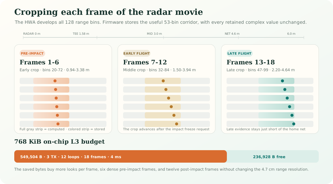
The planned 18-frame capture. Six dense pre-impact frames keep the near-tee corridor, six early-flight frames shift outward, and six late-flight frames finish just beyond the home net distance. One frame may already be armed when impact arrives, so firmware records the actual crop used by every frame rather than asking the Pi to assume the schedule.
Develop the full range picture
The Hardware Accelerator, or HWA, performs a 128-point range FFT for every chirp. That preserves the existing 4.7 cm range resolution while moving repetitive math off the CPU.
Real ADC tests, corner reflectors, and ball captures confirmed that the HWA can process the live signal and preserve the complex phase and amplitude needed for angle estimation.
Store a moving 53-bin crop
Instead of saving all 128 bins, EDMA copies 53 complex bins from the HWA into L3. The target crop moves through bins 20–72, 32–84, and 47–99 as the ball leaves the tee.
A geometry replay of 196 TrackMan-recorded trajectories, from sand wedge through driver, retained every modeled ball point that the previous fixed 80-bin capture could have retained. Hardware ball validation is next.
Freeze on a clean frame boundary
The ring continuously overwrites old history, like the OPS speed buffer. Impact tells the Pi to request a freeze; firmware then records a deliberate number of post-impact frames before stopping on a completed HWA/EDMA boundary.
Repeated clap, corner-reflector, and ball tests proved that the ring can freeze, dump, rearm, and capture again without relying on a seven-second host-side delay.
Reinvest the saved memory
The next candidate records 3 TX, 12 loops, 18 frames, and 4 ms spacing. That is 20% more per-transmitter looks, 50% more frames, and a denser view of the club approaching impact.
The linker proves it uses 549,504 of 786,432 L3 bytes, leaving 236,928 bytes for safety and future capture modes. Repeated home captures proved freeze, transfer, decode, and rearm; the July 22 TrackMan session confirmed approximately 0.68° vertical MAE on the matched capture group.
Where the L3 budget went
The first reduction proved the idea with a fixed 80-bin crop. The moving 53-bin version goes further, then spends part of the savings on better time resolution rather than merely producing the smallest file.
| Capture design | Geometry | L3 ring | Meaning |
|---|---|---|---|
| Original vertical baseline | 2 TX · 16 loops · 12 frames · 128 samples | 786,432 B | Proven TrackMan evidence, but no room for TX2 or more frames. |
| Raw three-TX proof | 3 TX · 10 loops · 12 frames · 128 samples | 737,280 B | Added aim, but spent almost the entire ring. |
| Fixed range snapshot | 3 TX · 10 loops · 12 frames · 80 bins | 460,800 B | Hardware proof that the chip can store FFT output instead of raw ADC. |
| Moving range crop | 3 TX · 10 loops · 12 frames · 53 bins | 305,280 B | Smallest current ring while retaining the modeled flight corridor. |
| Production capture | 3 TX · 12 loops · 18 frames · 53 bins | 549,504 B | Reinvests memory in stronger, denser club and ball evidence while preserving sub-1° vertical MAE. |
Four words that make the firmware easier to follow
| Word | Plain-language meaning |
|---|---|
| Frame | One radar movie frame containing a short burst of measurements from every active antenna. |
| Loop | One pass through TX1, TX2, and TX3. More loops provide more looks inside one frame. |
| Range bin | One approximately 4.7 cm distance slice between the radar and the net. |
| Complex I/Q | The amplitude and phase evidence retained for tracking speed and angle. The crop preserves both. |
What is proven, and what is not
| Finding | Status | Evidence |
|---|---|---|
| On-chip range FFT preserves usable complex antenna evidence | Hardware proven | HWA self-tests, real ADC tests, corner reflectors, and ball captures. |
| Selected bins can continuously fill and rearm a compact L3 ring | Hardware proven | Repeated boundary-frozen captures without short dumps. |
| All three transmitters retain detectable vertical and horizontal motion | Outdoor proven | Vertical launch remained plausible and intentional left/right groups separated. Horizontal accuracy still lacks TrackMan truth. |
| The 53-bin schedule covers normal launch-monitor trajectories | Replay supported | 196 TrackMan trajectories modeled through the proposed early, middle, and late windows. |
| 12 loops and 18 four-millisecond frames fit and decode correctly | Hardware proven | Firmware linker map, exact-geometry host regression, repeated home shots, and matched TrackMan captures. |
| The new firmware maintains sub-1° launch-angle MAE | TrackMan confirmed | Approximately 0.68° MAE on 20 matched July 22 captures using the measured 12.4° mount geometry. |
| Denser frames improve driver, club path, and attack angle | TrackMan pending | The extra pre-impact points are physically promising, but improvement has not been scored. |
Note
What cropping could miss: a badly entered tee or net distance, unusual trigger timing, an extreme mishit, or an unexpected reflection could place useful energy outside the saved corridor. That is why the three windows are 2.48 m wide, overlap heavily, and record their actual starting bin in every frame. Runtime tee/net-aware presets come only after the fixed schedule passes TrackMan.
What remains
| Work | Question it answers | Next proof |
|---|---|---|
| Independent firmware holdout | Does the 12-loop/18-frame result repeat after moving the rig and measuring geometry from scratch? | Repeat the production capture in another bay without fitting tilt from the scored block. |
| Capture coverage | Why did five TrackMan swings lack a corresponding OpenFlight/TI capture? | Separate trigger, OPS-shot, UART, and estimator denominators in the next truth session. |
| Driver recovery | Do 4 ms frames expose the real fast ball before a close net? | Compare tracked TI speed with OPS and TrackMan; reject slow ghost tracks. |
| Horizontal launch | Does TX2 measure degrees, not merely left/right sign? | TrackMan launch-direction MAE, bias, and coverage. |
| Club delivery | Do six dense pre-impact frames improve club path and attack angle? | Score against TrackMan club data without changing the ball estimator. |
| Sparse swing history | Can a second low-cost ring retain club-parallel-to-club-parallel motion? | First prove the dense frames consistently identify the club head. |
| Club and room presets | Should driver favor cadence while wedges favor deeper evidence, and should the crop follow net distance? | Only after one global configuration establishes an unbiased baseline. |
| Production calibration | Can multiple boards share one estimator? | Per-unit phase/gain calibration, enclosure tests, and eventual custom-PCB validation. |
Recommended validation order
- Repeat the 549,542-byte production capture in an independent bay with geometry measured before scoring.
- Separate trigger coverage, matched-capture coverage, estimator coverage, and accuracy in the session report.
- Score horizontal coverage, bias, MAE, P50, P75, and P90 before changing thresholds.
- Test 14 loops only if 12 loops show a quality or coverage limitation worth spending another 91,584 bytes.
- Use the remaining L3 budget for club-aware presets or sparse swing history only after ball-angle performance is protected.
Note
Bottom line: the chip did not need more memory; it needed a better editor. On-chip HWA processing and frame-aware cropping let us keep the radar evidence that can affect the answer, discard distance slices the ball cannot occupy, and spend the recovered budget on a denser club-and-ball movie. TrackMan now decides whether that engineering improvement becomes a product improvement.