Sound Trigger Wiring Guide
Step-by-step instructions for wiring the sound trigger that enables spin detection in rolling buffer mode.
Parts needed: See the Parts List for what to buy.
Running the OPS243 on the Pi GPIO UART instead of USB? This trigger wiring is unchanged —
GATEstill drivesHOST_INTdirectly. See Moving the OPS243 from USB to the Pi GPIO UART for the data and power side.
Overview
The SparkFun SEN-14262 sound detector listens for club impact and triggers the OPS243-A radar to dump its I/Q buffer. That captured data is then analyzed for spin rate estimation.
The wiring is simple — three wires off the detector, plus the radar's ground return:
SEN-14262 GATE → OPS243-A HOST_INT (J3 Pin 3)
SEN-14262 VCC  → Raspberry Pi 3.3V
SEN-14262 GND  → Raspberry Pi GND
OPS243-A GND   → Raspberry Pi GND (J3 Pin 10, shared rail)
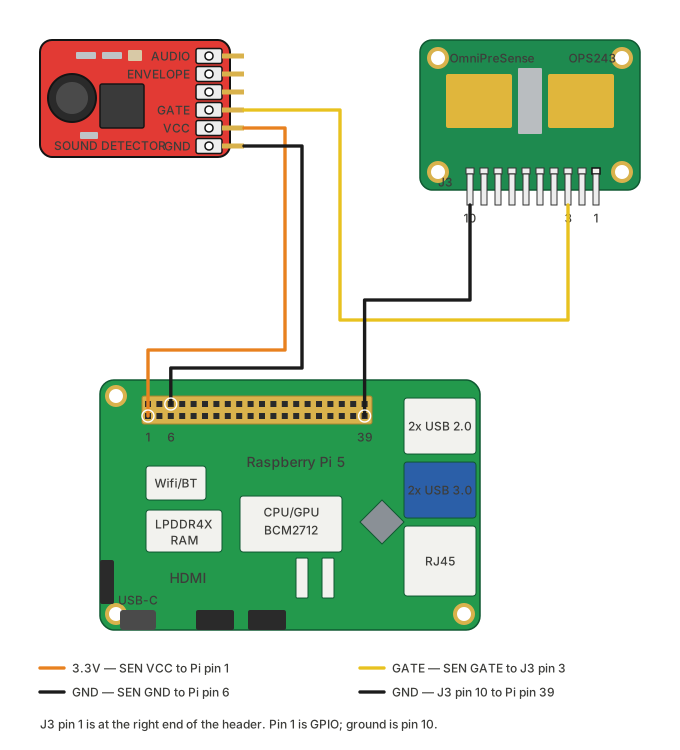
The OPS243 keeps its micro-USB connection for data and power here; only the trigger and ground are wired by hand. To take the radar off USB as well, see the UART migration.
Before You Wire: Solder R17
The SEN-14262 is designed for 5V but runs at 3.3V in this setup. At 3.3V the preamp gain is too high and the GATE output can get stuck high. To fix this, solder a through-hole resistor into the R17 position on the SEN-14262 board.
R17 sits in parallel with the onboard 100kΩ surface-mount R3, reducing the preamp gain:
| R17 Value | Effective Resistance | Gain Reduction |
|---|---|---|
| 47kΩ | ~32kΩ | Moderate — try this first |
| 33kΩ | ~25kΩ | More aggressive — for noisy environments |
Start with 47kΩ. If the GATE LED still stays lit without sound, switch to a lower value.
Wiring
Step 1: Identify OPS243-A J3 Header Pins
J3 is the 10-pin header on the OPS243-A. Pin 1 is at the right end, so
the numbering runs right to left:
OPS243-A J3 header:
┌────┬────┬────┬────┬────┬────┬────┬────┬────┬────┐
│ 10 │  9 │  8 │  7 │  6 │  5 │  4 │  3 │  2 │  1 │
│GND │ 5V │    │TxD │RxD │    │    │INT │    │IO  │
└────┴────┴────┴────┴────┴────┴────┴────┴────┴────┘
The two pins this guide needs:
- Pin 3 = HOST_INT (trigger input)
- Pin 10 = GND
Step 2: Connect Power
- Connect SEN-14262 VCC → Pi 3.3V (physical pin 1)
- Connect SEN-14262 GND → Pi GND (physical pin 6)
- Connect OPS243-A GND (J3 Pin 10) → same Pi GND rail
All three boards must share a common ground.
Step 3: Connect Trigger
- Connect SEN-14262 GATE → OPS243-A HOST_INT (J3 Pin 3)
That's it. No level shifter, no MOSFETs, no breadboard needed.
SEN-14262               Raspberry Pi           OPS243-A
┌───────────┐          ┌──────────┐          ┌──────────┐
│ VCC ──────┼──────────┤ 3.3V     │          │          │
│           │          │          │          │          │
│ GATE ─────┼──────────┼──────────┼──────────┤ HOST_INT │
│           │          │          │          │ (J3 P3)  │
│ GND ──────┼──────────┤ GND      ├──────────┤ GND      │
│           │          │          │          │ (J3 P10) │
└───────────┘          └──────────┘          └──────────┘
Wiring Checklist
- R17 resistor soldered on SEN-14262 board
- SEN-14262 VCC → Pi 3.3V (pin 1)
- SEN-14262 GND → Pi GND (pin 6)
- SEN-14262 GATE → OPS243-A HOST_INT (J3 Pin 3)
- OPS243-A GND (J3 Pin 10) → Pi GND (shared ground)
One-Time Radar Setup
With the wiring done, the OPS243-A needs rolling-buffer mode saved to
persistent flash before HOST_INT triggers will work.
Come back here for the trigger tests below once that is done.
Testing
Quick Test: Visual
Make a loud sound near the SEN-14262. The onboard LED should flash briefly, then turn off. If the LED stays on constantly, you need a lower-value resistor in R17.
Full Test: Software
You should see:
Ready for hardware sound triggers!
Make a sound near the sensor... (Ctrl+C to quit)

[1] Waiting for hardware trigger (timeout=60s)...
  TRIGGER RECEIVED after 0.02s!
  I/Q samples: 4096 I, 4096 Q
Troubleshooting
GATE LED stays on (stuck high)
The preamp gain is too high for 3.3V operation. - Fix: Solder a lower-value resistor into R17 (try 33kΩ instead of 47kΩ)
No trigger received
- Check the GATE LED flashes when you clap
- Verify GND is shared between all three boards (Pi, SEN-14262, OPS243-A)
- Verify HOST_INT is J3 Pin 3 (not Pin 2)
- Run
uv run python scripts/hardware-test/test_rolling_buffer_persist.py --testto confirm radar is in rolling buffer mode
Triggers constantly / too sensitive
- Use a lower-value R17 resistor to reduce gain
- Move the sensor further from the hitting area
Triggers but no I/Q data
- Run the one-time radar setup (see above) — HOST_INT mode must be saved to flash
- Power cycle the radar after setup